Drawing as
Transformation: From Primary Geometry to Secondary Geometry: Howard Riley
Abstract
A distinction is made between primary geometry, the arrangement in space of
lines of projection from a 3-D object to a plane of projection, and secondary
geometry, the relationships between the points, lines and shapes of the drawn
projection on a 2-D surface. Drawing projection systems, such as those
classified under British Standard 1192, are illustrated, and are shown to be
defined in terms of primary geometry. It is argued that John Willats'
re-classification of projection systems in terms of secondary geometry enables
first-year students of drawing to relate more easily such systems of geometry
to their observational experiences. Student drawings illustrate the argument.
Drawing
Conventions
Following the criteria of David Marr's [1] definition of a representation as a
"formal system for making explicit certain entities or types of
information, together with a specification of how the system does this",
it may be argued that projective geometry is such a means of representation,
because it provides a formal systematic procedure for making explicit
information about the three-dimensional attributes of objects and spaces upon a
two-dimensional surface. There are other formal geometric systems which have
been devised to represent such information. The various sets of rules which specify
how the procedure may operate are termed drawing conventions. British Standard
1192 [2] categorises these conventions:
|
|
Figure 1. B.S. 1192 categories of
projection types.
In this
classification, all orthographic and oblique projections may be specified as
parallel projection systems, since their projectors, those lines of projection
that link salient features of the object to points on the plane of projection,
are parallel. Perspective projections may be classified as convergent since
their projectors converge on a point in front of the plane of projection,
assumed to be a viewer's eye.
Orthographic
projection systems
- Multi-plane orthographic projection
This allows several views of an object to be projected upon several planes, assumed to be at right angles to each other: Projectors are parallel and are perpendicular to the planes of projection. Each object face is parallel with its plane of projection. - Axonometric, or single-plane orthographic projection
Projectors are parallel and perpendicular to the plane of projection, and all object faces are inclined to the plane of projection. Isometric Projection is a unique case of axonometric in which foreshortening on all three axes is the same. Dimetric projection is a special case of axonometric in which scales along two axes are equal, the third axis being different. Trimetric projection is the general case of axonometric and occurs when all three axes are randomly orientated and are each of different scales.
Oblique
projection systems
Oblique projections all have one face of the object parallel to the plane of
projection, and the projectors, although parallel to each other, are inclined
to the plane of projection in various ways.
- Cavalier oblique projection
The front face of the object is parallel with the plane of projection, while the projectors from the front face are perpendicular to the plane of projection. The projectors from the other two visible faces, although parallel, are inclined to the plane of projection so that the receding edges are represented at the same true scale as the front face. - Cabinet oblique projection is similar to Cavalier, except receding edges are
drawn to half the scale of the true front face projection.
- Planometric oblique projection is a special case of oblique projection, often
inaccurately called 'axonometric', where the plan face of the object is
parallel to the plane of projection (and usually rotated through 45º) and
projectors are inclined obliquely to the plane of projection.
Two other
forms of oblique projection, not identified in the British Standard have been
codified by Fred Dubery and John Willats [3]. They are:
- Horizontal oblique projection. One face of the object remains parallel to the plane
of projection and projectors are parallel, but are inclined to the plane
of projection in the horizontal direction only.
- Vertical oblique projection. One face of the object is parallel to the plane of
projection, the projectors are parallel but inclined to the plane of
projection in the vertical direction only.
Perspective
Projection
This family of projection conventions as defined by BS 1192 differs from
orthographic and oblique projections because the projected lines from the
object to the plane of projection are not parallel, but converge to a point,
generally regarded as the position of an observer's eye. The picture is formed
by the intersection of all these projectors with the plane of projection,
usually termed the picture plane in perspective projections. Parallel edges on
the object appear in the projected picture as orthogonals converging to a
point, known as a vanishing point.
- Parallel perspective
The object has its face parallel to and at right angles to the picture plane. Projectors converge to a point. - Angular (2-point) perspective
Vertical faces of the object are inclined to picture-plane, horizontal faces remain normal to the picture-plane: - Three-point perspective
All the object's faces are inclined to the picture-plane. There are three vanishing points
Primary
geometry and secondary geometry
Peter Jeffrey Booker [4] made the distinction between primary geometry, the
arrangement in space of lines of projection from the three-dimensional object
to the plane of projection, and secondary geometry, the relationships between
the points, lines and shapes of the drawn projection on a two-dimensional
surface. The projection types of B.S. 1192 discussed above are defined in terms
of primary geometry, but perhaps do not relate easily to students'
observational experiences.
|
|
Figure 2. John Willats'
Re-classification of B.S. 1192 in terms of secondary geometry.
John
Willats [5] has usefully re-classified B.S. 1192 in terms of secondary
geometry. For example, in the original B.S. 1192, axonometric drawings showing
three faces of an object have to be classified with orthographic projections
which show only one face, because their primary geometries have parallel,
perpendicular projectors in common. Willats suggests it would be beneficial to
re-classify the axonometrics under oblique projections, thus recognising their
obvious similarities of secondary geometry, which are the number of faces shown
in the drawings, and, the directions of their orthogonals.
This
re-classification of drawings in terms of their secondary geometry provides a
way of understanding those drawings which do not depend upon the drawer's
position defined by primary geometry but which, in their secondary geometry,
explicate features of the object that are known, but not necessarily visible to
the drawer.
Viewer-Centred
and Object-Centred Representations
These terms derive from the investigations of Marr and Nishihara [6] into the
representation and recognition of the spatial orientation of objects. The two
categories are implicit in the classification of projection types. Therefore it
may be useful to review those again, this time relating primary and secondary
geometries to viewer - and object-centred representations. According to Marr
and Nishihara, vision is the processing of information derived from two-dimensional
retinal images (viewer-centred) so as to produce information that allows us to
recognise three-dimensional objects (object-centred descriptions). The organic
visual system receives at the retinae constantly changing arrays of light
reflected from surfaces and objects in the world from which we derive
representations of those surfaces and objects that are consistent, as well as
unchanging across varying viewpoints and lighting conditions. Such
representations may take the visible form of drawings not readily classifiable
under the rules of primary geometry which are based upon specific assumed
viewing positions. Willats' work over a period of time has synthesised aspects
of Marr's theory into a unique approach to the understanding of children's drawings
and others whose drawings cannot be defined in terms of primary geometry, but
may be understood as examples of the following three categories:
Divergent
perspective This term describes drawings in
which the orthogonals diverge. Although strange to Western eyes, Willats points
out that this system, together with horizontal oblique projection, was the most
commonly used in Byzantine art and Russian icon painting during a period of
over a thousand years. Figure 3 illustrates a more recent example, Picasso's
Woman and Mirror, 1937.
|
|
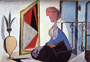
Figure 3. Woman and Mirror,
Pablo Picasso, 1937.
Topological
geometry Drawings which map spatial
relations such as connections, separation, and enclosure, rather than
resemblance and accurate scale, make use of topological geometry. Such drawings
may be more easily understood in terms of an object-centred secondary geometry.
Australian aborigine art is often constructed using topological geometry.
Figure 4 illustrates the artist Uta Uta Tjingala's painting Kaakurnatintja (not
dated) which represents the spatial connections between water-holes and other
important locations.
|
|
Figure 4. |

"Fold-out"
drawings and multiple-view drawings
These drawings display information about various aspects of objects and spaces
simultaneously. This is not possible in drawings dependent on single-plane
projections based on primary geometry. In Figure 5, Bhawani Das' Aurangzeb and
Courtiers, c1710, the ground plane has been folded down in orthographic
projection in order to convey information otherwise not available from a
viewer's position perpendicular to the picture-plane. In the same drawing, the
canopy has been rendered in axonometric projection, allowing the viewer a
top-view which, whilst inconsistent with the obliquely-projected footstool,
affords extra information about the scene.
|
|
Figure 5. |

To
continue with the review of projection types in relation to viewer-centred or
object-centred representations:
Multi-plane
orthographic projection These
drawings are independent of any single viewing position, and are useful for
describing the true proportions and relationships between faces of a
three-dimensional object. This projection has become the standard for engineers
and architects.
Oblique
projections These may be constructed to
describe properties of either an object or interior spaces which would not be
visible from certain viewer-centred positions. Figure 6, a Punjabi painting The
Gale of Love, c1810, shows interiors of rooms left and right, which would not
be possible in a viewer-centred description.
|
|
Figure 6. |

Types of
oblique projection are evident in drawings from various cultures and periods.
In the West, an early description of oblique projection was given by Cennino
Cennini [7] who advised the artist to
...put in
the buildings by this uniform system: that the mouldings which you make at the
top of the building should slant downward from the edge next to the roof; the
moulding in the middle of the building, halfway up the face, must be quite
level and even; the moulding at the base of the building underneath must slope
upward, in the opposite sense to the upper moulding, which slants downward.
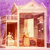
That this
advice had already been understood by painters is apparent from Figure 7
painted by Giotto in the Capella degli Scrovegni at Padua between 1304 and
1308.
|
|
Figure 7. |
One-point,
Artificial Perspective This is a
projection system whose primary geometry is based upon what James J. Gibson [8]
termed the natural perspective of an array of light reflected from surfaces and
converging on the eye. It assumes the viewing position is singular, and static.
In terms of secondary geometry, all orthogonals converge on a point known as
the vanishing point. Its invention was the culmination of a long-standing
desire to produce what Martin Kemp [9] described as "the imitation of
measurable space on a flat surface". As such, it may be understood as a
more rational codification of the former, loose method practised by Giotto and described
by Cennini. Most authorities agree that linear, one-point perspective was
invented by Filippo Brunelleschi in Florence. Kemp [10] cites a source which
suggests the date of 1413. It is certain that the system was codified and
published in Latin by Leon Battista Alberti in 1435. The Italian version of
1436 had a prologue addressed to Brunelleschi and explained the primary
geometry of light rays reflected from surfaces regarded as the base of a
pyramid and converging to an apex at the painter's fixed eye.
Students'
Drawings
Each one of the ways of drawing discussed above makes certain information about
three-dimensional objects and spaces explicit, but at the expense of other
information which is obscured. Therefore the choice of a particular way of
drawing will depend upon what specific information about the scene, as well as
the viewer's position relative to the scene, is deemed important enough to be
represented in the drawing. Moreover, such decisions will vary according to the
intended purpose of the drawing, for whom it is intended, and according to the
socially-conditioned ways that people construe the relationship between
themselves and their environment at different ages and in different periods of
history. It is these relationships between drawing and social context that are
explored in the drawing studio.
The studio
drawing project afforded students the opportunity to relate the concepts of
primary geometry and secondary geometry to those of viewer- and object-centred
representations through their drawing practice. It may be pertinent to note
here that few first-year undergraduates came to the programme with a firm grasp
of any geometry , so that for many, this project became an opportunity to
explore such basics as orthographic, oblique and perspective projection systems
of secondary geometry.
|
|
Figures 8(left), 9 and 10 (below) |
|
|
|
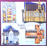
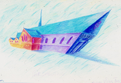
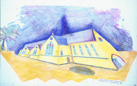
Drawings
from the 'Geometries of Vision' project.
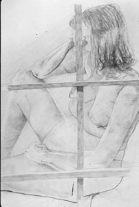
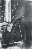
Figure 11 illustrates student inquiry into the assumption implicit in
perspective projection, that of the fixed, single point of viewing. Here is an
attempt to break out from such ontological constraints, and to invent a way of
representing the information in the light received at both eyes. Focusing upon
the wooden framework with each eye in turn, but paying attention to the primary
geometry of the scene, the student shares the experience of both eyes in the
one drawing. The primary geometry of the scene is transformed into a secondary
geometry rarely explored.
|
|
Figure 11. |
The
drawing illustrated in Figure 12 evolved from the student's study of projective
geometry systems in common usage. An awareness that all of those assumed a flat
plane of projection stimulated inquiry into the possibility of projecting onto
a non-flat plane. Discussion around the notion of a 'cone of vision' developed
into the idea of inventing a system for geometrically projecting what was noticed
in the cone of vision onto a cone of projection. A paper cone was duly
constructed and arranged at eye level, apex pointing to eye. With one eye
closed, so as to flatten the cone perceptually, the student proceeded to mark
the cone at appropriate distances from the eye, the marks representing the
salient scene primitives (corners and edges). When the paper cone (or pyramid,
to be precise) was laid out as a surface development, an original projection
system was revealed.
|
|
Figure 12. |
Figures 13
and 14 illustrate two students' efforts to explore the inter-relationships
between primary geometry, secondary geometry, and viewer-centred and
object-centred representations. Figure 13 attempts to employ a secondary
geometry constructed from the combination of a viewer-centred representation
(that of the figure itself) and several views of the wooden frame which made up
the subject-matter. Such multiple views of a single object have the effect of
increasing our information of the object as if we were able to move forwards
around it. Such object-centred representations combined with a viewer-centred
representation of the figure produces a drawing in which the viewer's position
is ambiguous.
|
|
|
Figures 13(far left) |
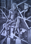
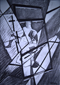
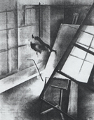
Figure 14
attempts a further complication. Here the figure itself is represented as
mirrored, and the wooden frame appears in front of the figure and behind the
figure simultaneously, as well as forming the geometry of the space within
which the figure exists. The effect upon the viewer is that of a shattered
image, dynamic and excited. This exercise stimulated the student to further
explore the possibilities of combining viewer- and object-centred
representations in a drawing.
|
|
Figures 15(left) |
|
|
|
|
|
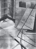
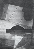
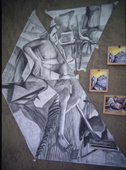
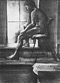
The series
of drawings, Figure 15, a, b, c and d, illustrates a systematic approach to the
exploration of a possible transition from a viewer-centred representation to an
object-centred one. Figure 15 was drawn from a (relatively) fixed position and
indicates the student's grasp of the transformation process from primary
geometry to a viewer-centred secondary geometry. As the series progresses (15
a, b, c & d) lines and contrast-boundaries between tones representing the
salient edges in the scene become interlocked, producing a complex web of
compositional axes. This pictorial device enables the viewer to see
relationships between those edges defining the space which are not available
from a fixed viewing position. As more information about spatial relationships
is added, less is revealed of the viewer-centred representation of the figure
within the space. Finally, in Figure 15d, the figure is transformed through
geometry into pure organic form.
The
research is ongoing. Critical comment is welcome.
References
1. Marr, D. 1982 Vision. A Computational Investigation into the Human
Representation and Processing of Visual Information. New York: W. H.
Freeman
2. Recommendations for Building Drawing Practice. B. S. 1192 1969
London: British Standards Institution pp. 31-34
3. Dubery, F. & Willats. J. 1983 Perspective and other Drawing Systems.
London: The Herbert Press
4. Booker, P. J. 1963 A History of Engineering Drawing. London: Chatto
Windus
5. Willats, J. 1997 Art and Representation. New Principles in the Analysis
of Pictures. New Jersey: Princeton U.P.
6. Marr, D. & Nishihara, H. K. 1978 Representation and recognition of the
spatial organisation of three-dimensional shapes. Proceedings of the Royal
Society, London Series B200 pp. 269-294
7. Cennini, C. 1390 The Craftsman's Handbook. Transl. by Thompson, D. V.
1933 New York: Yale U.P. Reprinted 1960, Dover Publications
8. Gibson, J. J. 1979 The Ecological Approach to Visual Perception.
Boston, Mass: Houghton Mifflin
9. Kemp, M. 1990 The Science of Art: Optical Themes in Western Art from
Brunelleschi to Seurat. New Haven, Conn: Yale U.P.
10. Ibid. p.9
Dr Howard Riley MA(Royal College of Art), PhD
School of Art & Design
Swansea Institute of Higher Education
Swansea, Wales, UK
howard.riley@sihe.ac.uk